
Compressed Biogas Unit
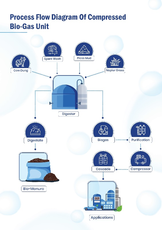
The world is rapidly moving towards sustainable and renewable sources of energy, and compressed biogas (CBG) seems to be the fuel of the future. CBG is a clean and green energy source produced from the effluents such as Spent wash, press mud, Napier grass and decomposition of organic waste. The process of producing CBG involves the collection of organic waste and the conversion of this waste into biogas through anaerobic digestion. This biogas is then compressed to increase its density and stored for future use. Overall, the adoption of CBG as a fuel of the future is a step in the right direction towards a cleaner, greener, and more sustainable future.
Process Flow Diagram of CBG
Process :
Biogas Generation :
The reactors employed for this
purpose
adhere to a Continuous
Stirred Tank Reactor (CSTR) configuration, characterized by their operational dynamics.
These reactors function optimally under mesophilic temperatures, which are moderate and
conducive to the efficient biogas generation process. This strategic alignment enhances the
overall efficiency and performance of the system, leading to the successful conversion of
organic waste into valuable biogas while maintaining operational robustness.
Biogas Cleaning Process :
This cutting-edge Indian technology elevates biogas purity beyond
96% methane gas, adhering to government standards. The weather-resistant absorber columns
efficiently eliminate H2S and CO2. The interconnected upgradation sections maintain uniform
gas pressure via a central gas holder, backed by safety valves and sensors tied to a PLC for
comprehensive safety. The process begins with raw biogas from digesters treating distillery
waste and press mud. An innovative biochemical method, including an aerobic reactor,
absorber, and sulphur recovery unit, converts H2S-containing gases to elemental sulphur. The
resulting biogas, with reduced H2S at 200 ppm, undergoes further refining through a
low-pressure compressor unit. Real-time monitoring is facilitated by online H2S analyzers,
enhancing control, and accuracy.
Co2 removal from biogas employs a packed column with soft water as solvent under 7.5 kg/cm² pressure, reducing CO2 to <4%. A closed-loop system regenerates soft water, minimizing chilling costs. Moisture removal follows via a Dryer Unit. Dry methane, free of H2S and CO2, is achieved through a two vessel molecular sieve dryer. Biogas then enters a 6-7 kg/cm² buffer vessel with pressure control and PRV for closed-loop gas recycling, before advancing to the high-pressure compressor
Cascade Filling :
Cascade filling is a method to
efficiently fill gas cylinders.
The
CBG is
to be compressed at 250 Bar and supplied through Cascades.
Features
- Fully automatic system to ensure smooth and easy operation.
- Sterile construction of equipment to maintain high hygiene level.
- Energy Efficient.
- Optimal space requirement.
- Carefully selected material of constructions taking into account the product properties.
- Complete sanitary design with CIP system.
- PLC controlled SCADA operated system.
Services
- Turnkey Plants.
- Manufacturing & Supply of Equipments.
- Engineering and Supervision of Civil and Structural work.
- Process and Detailed Engineering.
- Project Management.
- Commissioning and Training.

Copyright 2015. All Rights Reserved. Raj Group | Terms & Privacy Policy


